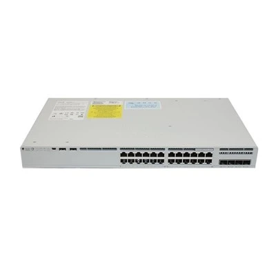


A DIN rail switch is the easiest part of a control cabinet to install and the easiest to install badly. Mounted with no clearance, fed from the same power supply as the drives, and packed next to heat sources, the unit runs hot, drops links under load, and takes the blame for faults that belong to the enclosure design. This guide covers the mounting, wiring and thermal rules that keep an industrial switch running for its rated life.

Why Mounting Detail Decides Reliability
Industrial switches are specified over wide temperature ranges, typically from −40 °C to +75 °C, but those figures assume free air around the enclosure and correct orientation. Inside a sealed cabinet the ambient temperature can be 20 °C above the room, and a device with no clearance on either side sits in its own exhaust. The result is not an immediate failure but a shortened life, intermittent link flaps and a device that resets during the hottest hour of the day.
A DIN rail switch also relies on the rail for mechanical integrity. The clip is designed for a standard 35 mm top-hat rail to EN 60715, and a switch that hangs from a damaged or non-standard rail moves under vibration, which eventually damages the RJ45 latches and the SFP cage.
Criterion 1: Rail, Orientation and Clearance
Mounting is specified, not improvised. Follow the manufacturer's stated clearance above, below and beside the device - commonly 25 mm or more above and below, and a similar gap each side for units with side ventilation, plus additional space in front of fiber cages for patch cords and their bend radius.
- Rail standard: 35 mm DIN rail to EN 60715, securely fixed to the panel.
- Orientation: only mount in the orientation the manual permits; many units are ventilated top and bottom.
- Clearance: respect the vertical gaps; hot air must leave the enclosure.
- Depth: allow for the cable bend radius in front of copper and fiber ports.
- Vibration: use end stops on the rail so the switch cannot slide.
- Weight: heavy PoE models may need a rail rated for the load or a support bracket.
Criterion 2: Power Supply and Redundant Inputs
Most industrial switches accept a wide DC input, often 12–48 V DC or 24 V DC nominal, and many offer redundant inputs with reverse polarity protection. Use that redundancy deliberately: two separate power supplies, ideally on separate feeds, means a single PSU failure does not take the network down.
- Separate supply for the DIN rail switch: do not tap the same 24 V rail that feeds contactors and drives.
- Protection: individual fuse or breaker per device, rated to the DIN rail switch's input current with margin.
- Sizing: include PoE load in the calculation; total budget plus DIN rail switch consumption determines the PSU rating.
- Voltage drop: long runs of thin cable may present less than the minimum input voltage at the device.
- Terminal torque: use ferrules and tighten to the stated torque; loose terminals arc and overheat.
- Labelling: mark each feed and its breaker, so a future technician can isolate the right circuit.
Criterion 3: Grounding and Cable Routing
Grounding is where cabinets most often compromise a network. The switch's earth terminal must be bonded to the panel earth with a short, low-impedance conductor, and shielded cabling must be earthed at one end only unless the installation is designed otherwise.
Cable routing matters as much as grounding. Data cables run parallel to motor and drive cables pick up noise inductively, and the effect scales with distance and with how close the cables run.
- Separation: keep data cabling away from drive and motor cabling; cross at right angles if unavoidable.
- No shared trays: do not use the same duct for 400 V power and Ethernet if there is any alternative.
- Shield handling: earth the shield at one end, or use a properly designed industrial system.
- Bonding: in cabinets with VFDs use the panel's bonding system rather than relying on the DIN rail's contact.
- Patch cords: use industrial-rated cords with adequate strain relief, not office patch leads.
Criterion 4: Thermal Load and Cooling
The heat a DIN rail switch produces includes its own losses plus, on PoE models, the losses in the PoE supply path. In a sealed enclosure that heat accumulates, and the internal temperature can exceed the switch's rating even though the room is comfortable.
| Cooling approach | When it fits |
|---|---|
| Passive, with clearance and vents | Low-density cabinets in a temperature-controlled room |
| Filtered fan and lower vent | Medium-density cabinets, dusty but not wet environments |
| Enclosure air conditioner | High ambient, sealed cabinets, washdown areas |
| Heat exchanger | Sealed cabinets where dust or moisture ingress is unacceptable |
Whichever method you choose, measure rather than assume. A temperature logger inside the cabinet over a full production week tells you whether the DIN rail switch is operating inside its ratings, and it is cheaper than the downtime caused by discovering the answer the hard way.
- Measure at: the switch's air inlet, not on the panel door.
- Worst case: summer afternoon with all drives running.
- Consider derating: many vendors derate total PoE budget above a stated ambient, such as 45 °C or 60 °C.
- Keep clear: do not place the DIN rail switch directly above a drive, transformer or braking resistor.
Criterion 5: PoE Budget and Cabinet Reality
PoE models concentrate more heat in the same small form factor, so the power budget and the thermal budget must be calculated together. A switch rated 240 W of PoE in free air may only deliver a reduced figure at 60 °C inside an enclosure, and the difference can be exactly the margin the cameras needed.
- Total budget: sum device classes, then add the headroom rule from the deployment plan.
- Derating curve: find the stated ambient above which the PoE budget is reduced.
- Cable heating: bundled PoE cables add to cabinet heat.
- Spare capacity: plan for one added camera without exceeding the derated budget.
- Monitoring: if the switch reports PoE consumption, read it during commissioning and record the figure.
Criterion 6: Commissioning Checks
Commissioning is the last chance to catch installation faults cheaply. A short, disciplined checklist prevents most of the call-backs that follow a rushed cabinet build.
- Verify input voltage at the switch terminals under load, not at the PSU.
- Confirm redundant feeds are on separate circuits.
- Check earth bonding resistance and terminal torque.
- Record cabinet temperature after two hours of full operation.
- Confirm link speeds and error counters on every port.
- Read optical power on fiber uplinks and record the values.
- Save the DIN rail switch configuration and store it off the device.
- Photograph the finished cabinet and file it with the network records.
Common Mistakes Installers Make
- Mounting with no clearance. The device runs at its own exhaust temperature and fails early.
- Sharing the drive supply. Noise and voltage dips on the 24 V rail propagate into the network.
- Ignoring the orientation requirement. Some units rely on vertical airflow and derate when mounted otherwise.
- Using office patch leads. Thin cords without strain relief fail at the latch, not in the middle.
- Assuming PoE budget is constant. Above a stated ambient the available budget shrinks.
- Skipping the temperature measurement. The number is either known or it is a guess.
- No configuration backup. A replacement then takes an experienced engineer instead of a technician.
FAQ
Q1: How much clearance does a DIN rail switch need?
Follow the manual, but plan on at least 25 mm above and below and a similar gap to each side, plus space in front for cable bend radius. Units with side ventilation need clearance on those faces too.
Q2: Can a DIN rail switch be mounted horizontally or on its side?
Only if the manufacturer permits it. Many designs assume a defined airflow direction and must be derated when rotated, so check the datasheet before choosing an orientation that suits the cabinet layout.
Q3: Should a DIN rail switch have its own power supply?
Yes, ideally. Feeding the DIN rail switch from the same rail as drives exposes it to voltage dips and noise, and a dedicated supply with a separate feed makes the network independent of motor-side faults.
Q4: How hot is too hot inside a cabinet?
Compare the measured air temperature at the switch inlet with the device's rated maximum, and remember that above a stated ambient many PoE models derate their power budget. Measure during the hottest production conditions rather than the first cool morning.
Q5: Do I need shielded cable in an industrial cabinet?
Shielded cable helps where drives are present, but the shield must be terminated correctly at one end. Route data away from power first - separation usually solves more than shielding does.
Q6: How do I protect a DIN rail switch from vibration?
Fix the rail securely, fit end stops so the device cannot slide, use latching SFP modules and industrial patch cords with proper strain relief, and support heavy PoE models rather than hanging them on the clip.
Q7: What should I record at commissioning?
Input voltage under load, cabinet temperature after full-load running, port error counters, optical power on fiber links, and a saved configuration with a photograph of the cabinet. These five records resolve most future disputes.
Install It Once, Properly
A DIN rail switch rewards proper installation more than almost any other component in the cabinet, because the failures it suffers are almost always thermal, electrical or mechanical - and all three are decided during the build. Give it clearance, its own power, clean routing and a measured thermal margin, and the device will outlive the equipment around it.
AITI Tech Limited supplies DIN rail mounted industrial Ethernet switches, including wide-temperature and PoE models, with the mounting, power and thermal documentation needed for cabinet design. Send us your cabinet layout, ambient conditions and PoE device list, and our engineers will confirm the model, clearance and derated power budget before you build.